

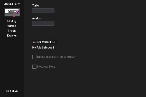
I made Cassettify because of a personal problem I had while adding custom songs to the game ROBOBEAT. The game allowed you to add custom songs and edit them, but the game was awful at detecting a song's beats and the external tools that allowed you to be able to detect the BPM of a song didn't work with songs that had a imperfectly consistent BPM.
The app gives more options to people looking to create custom songs in the game, listed below:
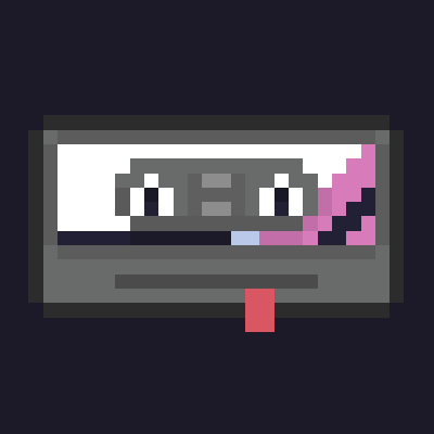
I am currently doing a full remake of this app in Electron due to many design and cross-platform restrictions that come with the tkinter library. You can find the github repository down below.
Github Repository
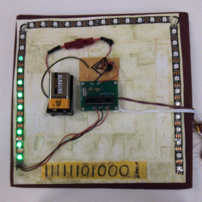
I had the idea to make this project after my art teacher in school gave us large square stickers that could be drawn on and put on the top of a graduation cap. He said, "Decorate them however you like," and I took that statement literally.
The circuit works by the 9V battery passing through a voltage converter, the light brown board, which reduces the voltage to 5V. This travels up to the circuit that sends the instructions to the LEDs, the green circuit board. The green circuit board contains a pre-programmed chip removed from an arduino, the ATMEGA328P chip. It was rewired for a smaller, permanent, form so it could fit well on the cap. The green circuit board was made by me using KiCad based on schematics from this guide.
The light pattern is based on a sine wave. The program simply loops and adds a small percentage of 2π every time it goes around. once it reaches 2π, it resets back to 0. It uses that number to display the pattern on the LED array by modifying the output of the sin() to match indexes on the array.
Unfortunately, I do not have the KiCad circuit board file or the code on the chip. They were both stored on a school computer and were deleted soon after I finished the project.
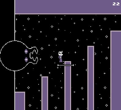
This game was part of a game jam I participated in that reqired me to make a game that felt like a game that could be on a game boy following the theme "Spooky" in just 10 days. Every part of the game was made by me aside from the font used in displaying score. I created the music using the game boy music sequencer LSDJ, the art with Aseprite, and the programming with the Godot game engine's language, GDScript. You can find the game's page down below.
Itch.io Page
An app I created on code.org's applab that tries to replicate the game osu!mania. I decided to try making this after realizing that applab had the timedLoop function and was able to take keyboard input outside of text boxes which would allow me to create frames and controllable objects, like in a game. Since the applab platform was not designed for creating games, only certain browsers with high performance like Microsoft Edge or Brave will run it well.
AppLab Page